3DVeniceWellheads: Difference between revisions
Loic.rochat (talk | contribs) |
|||
| (148 intermediate revisions by 3 users not shown) | |||
| Line 1: | Line 1: | ||
== | == Motivation == | ||
[[File:vere_rizzi.jpg |thumb| The Well-Heads of Venice – Alberto Rizzi]] | |||
Venice is one of the cities in Europe with the richest and largest number of [https://en.wikipedia.org/wiki/Puteal well-heads], locally known as ''Vere da Pozzo''. This term refers to the stone structure surrounding the pipe of a well with a protective function. Across history, the role of wells for Venice has always been crucial, in first place to assure drinking water for citizens. Although on water, the city needed wells to store unsalted water. They were placed most of the time in the middle of a square or a private courtyard to collect rainwater and filter it in the ground. In times of drought, they were filled with fresh water from the nearby Brenta river. | |||
Over time, the need and societal use of wells evolve along society. Once more than 6000 across all Venice, it is today estimated that more than 2300 well-heads are spread across the city. To better understand these changes, the goal of this digital humanities project is to digitize well-heads and thus provide additional material to upgrade the Venice 1808 digital Cadastre in development at the EPFL DH lab. | |||
The project uses the book ''Vere da Pozzo'' by Alberto Rizzi with circa 250 references of well-heads in the wider Venice islands. It lists photos, description of conservation, periods of construction, material, and overall dimensions. It is complemented with the GPS locations of well-heads in Venice available [http://cigno.atlantedellalaguna.it/maps/47/view here]. | |||
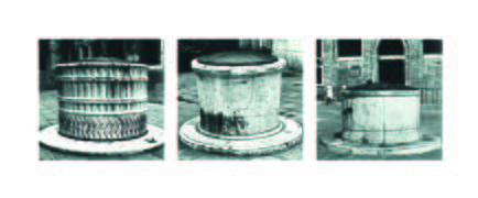
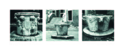
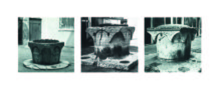
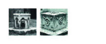
The material available limits the level of detail one can extract through digitization. Some wells are badly preserved and most of the time, only one photograph is provided. Pictures of well-heads are similar to a profile point of view but vary case by case. However, the material is good enough to give clear indications of the overall shape and the style adopted. The architectural styles of well-heads are thus the key elements to be successfully digitized in this project. It takes the form of 3D models semi-automatically generated out-of-the-book pictures. The reader could expect to recognize arches, geometrical symmetries, overall size, and moulding styles as differentiating elements of Venetian well-heads. Detailed sculptures won't be reproduced. | |||
== Outcome and deliverables == | |||
The deliverables are available on [https://github.com/CheminDavide/3DVeniceWells GitHub]. Here are the main elements: | |||
'''The tools:''' | |||
* Rhino Grasshopper script to model well-heads with arches, mouldings, and varying polygonal slabs. | |||
* Rhino Grasshopper script to extract the dimensions and store them into a JSON file. | |||
* Localization tool to match all the known GPS location of well heads with the ones of the book. | |||
* A Jupyter Notebook with python code to create the json catalogue file already filled with the available information (index, IDs and coordinates). | |||
'''The results:''' | |||
* Scanned images of ''Vere da Pozzo'' by Alberto Ricci. | |||
* Digitized well-heads in 3D model as .fbx files. | |||
* Related rendered images of the 3D models. | |||
* Associated JSON files with the dimensions of each well-head. | |||
* A comprehensive catalogue with reference to each well-heads with information like location, district, date, material, dimensions and links to 3D models and pictures. | |||
== Project Plan == | == Project Plan == | ||
The project is separated in three main goals: identify the historical document to use, develop the digitization methods and finally perform the digitization. The following table provides the project plan. | |||
{|class="wikitable" | {|class="wikitable" | ||
| Line 37: | Line 45: | ||
|By Week 4 | |By Week 4 | ||
| | | | ||
* | * Definition of the content and outcome of the project | ||
| align="center" | | | align="center" | ✓ | ||
|- | |- | ||
|By Week 5 | |By Week 5 | ||
| | | | ||
* | * Definition of the content and outcome of the project | ||
| align="center" | | * Rhino and Grasshopper tutorial | ||
| align="center" | ✓ | |||
|- | |- | ||
|By Week 6 | |By Week 6 | ||
| | | | ||
* | * Identification of well-heads typologies with the book ''Vere da Pozzo'' | ||
| align="center" | | * Use the typologies to define the model structure and parameters | ||
| align="center" | ✓ | |||
|- | |- | ||
|By Week 7 | |By Week 7 | ||
| | | | ||
* | * Design a grasshopper diagram for slabs and mouldings. Use input points as csv file. | ||
| align="center" | | | align="center" | ✓ | ||
|- | |- | ||
|By Week 8 | |By Week 8 | ||
| | | | ||
* | * Work on the 3D model | ||
| align="center" | | * Improve the Grasshopper model for slabs and mouldings. Eliminate issues and finalize the set of parameters used to describe the typologies of a well-head. | ||
* Prepare slides for the midterm project presentation. | |||
| align="center" |✓ | |||
|- | |- | ||
|By Week 9 | |By Week 9 | ||
| | | | ||
* | * Improve the Grasshopper model. Use of JSON file for the well-heads parameters. | ||
| align="center" | | * Identify how to extract the parameters out of the well-heads picture of the book. | ||
* Rehearse the midterm presentation | |||
| align="center" |✓ | |||
|- | |- | ||
|By Week 10 | |By Week 10 | ||
| | | | ||
* | * Midterm presentation | ||
| align="center" | | * Design a Grasshopper model to extract parameters from pictures and output a JSON file. | ||
* Scan the book ''Vere Da Pozzo'' | |||
| align="center" |✓ | |||
|- | |- | ||
|By Week 11 | |By Week 11 | ||
| | | | ||
* | * Definitive 3D model on Grasshopper. | ||
| align="center" | | * Generate semi-automatically the 3D models of well-heads. | ||
| align="center" | ✓ | |||
|- | |- | ||
|By Week 12 | |By Week 12 | ||
| | | | ||
* | * Create a JSON file with well-head ID, location coordinates, link to the 3D model, the square name, the construction time, the material and the height. | ||
| align="center" | | * Provide either the images of the well-heads through a unique PDF or as a set of individual files. | ||
* Finish to generate semi-automatically the 3D models of well-heads. | |||
| align="center" | ✓ | |||
|- | |- | ||
|By Week 13 | |By Week 13 | ||
| | | | ||
* | * Preparation for the final presentation | ||
| align="center" | | * Complete the wiki on motivation, methods, quality assessment, and limitations. | ||
* Time slot dedicated to diverse problem-solving cases. | |||
| align="center" | ✓ | |||
|- | |- | ||
|By Week 14 | |By Week 14 | ||
| | | | ||
* | * Final presentation | ||
| align="center" | | | align="center" | ✓ | ||
|- | |- | ||
|} | |} | ||
| Line 104: | Line 125: | ||
== Methodology == | == Methodology == | ||
The | The Venetian wells are magnificent, feature beautiful sculptures and pose a great challenge to digitize in 3D. Some project model buildings with photogrammetric technics. The availability of aerial videos provides multiple viewing angles and offer thus the possibility to use computer intensive algorithms and a mostly automated approach. This is not the case with well-heads, and it, therefore, asks us to adopt a different strategy. | ||
Common typologies of wells: | Few documents provide a comprehensive and systematic approach to the reproduction of well-heads. One of them is ''[https://archive.org/details/gri_33125013354838/mode/2up Raccolta delle vere da pozzo]'' by Ferd. Ongania published in 1889. It is the oldest and first one to reproduce well-heads with photography. It looks like a great photo album: quality photographs with names and places. The photo are adequate for modelling, however, they lack detailed metadata such as height to calibrate the 3d models. That's why the project selected a more recent catalogue, Alberto Rizzi's book. It features a smaller number of well heads but with the metadata required. Below, two images of Ongania and Rizzi's books. | ||
{| class="wikitable" style="margin: 1em auto 1em auto;" | |||
| [[File:raccolta-delle vere-da-pozzo.jpg|none|thumb|500px| Raccolta delle vere da pozzo, Ferd. Ongania, 1889]] | |||
| [[File:vere-da-pozzo.jpg|none|thumb|500px| Vere Da Pozzo Di Venezia, Alberto Rizzi, La Stamperia Di Venezia Editrice, 1981]] | |||
|} | |||
===Typologies and procedural modelling=== | |||
To model a well-head, one ideally needs to get a perspective of all viewing angles. In this case, only one picture from the side is given. The modelization then takes into consideration additional information and compensates for this information asymmetry. The well-head is symmetric and features specific architectural styles. The goal is to identify the most basic typologies of wells with basic geometric shapes and use them to model a simple shape of each well with Rhino Grasshopper. | |||
Common typologies of wells in Venice: | |||
* Base with circular, square, hexagonal, octagonal, decagonal (10), dodecagonal (12) shapes. | * Base with circular, square, hexagonal, octagonal, decagonal (10), dodecagonal (12) shapes. | ||
* Top with circular, square, hexagonal, octagonal, decagonal (10), dodecagonal (12) shapes. | * Top with circular, square, hexagonal, octagonal, decagonal (10), dodecagonal (12) shapes. | ||
* Edges are either sharp or embedding a sculpture that cut them. | * Edges are either sharp or embedding a sculpture that cut them. | ||
* Well-heads rest on a slab with one, two or three steps. | * Well-heads rest on a slab with one, two or three steps. | ||
* Top | * Top 15-30cm of the well either have flanges with square or circular profiles or arcades | ||
Additionally, one notes that architectural styles and typologies also refer to the historical periods. This approach is thus relevant from a historical point of view, and the later digital historian will be able to use 3D models such as the ones developed in this project. Below is a table with the classification by stylistic appearance and historical period of well-heads: | |||
{|class="wikitable" | |||
! style="text-align:center;"|Type | |||
! Period | |||
! Features | |||
|- | |||
|Archeological | |||
|Greek and Roman | |||
|Rough, made from column shafts, altars, memorial stones, cinerary urns and other pieces. | |||
|- | |||
|Carolingian | |||
|''VIII-X'' centuries | |||
|Cubic, decorated with symbols of Christian art | |||
|- | |||
|Venetian-Byzantine | |||
|''XI-XIII'' centuries | |||
|Free-standing cylinder decorated with pillars or columns | |||
|- | |||
|Gothic | |||
|''XIV-XV'' centuries | |||
|Like capitals of columns or pillars, with square frame | |||
|- | |||
|Traditional | |||
|''from 1300'' | |||
|Cylindrical shaft with small arches in the corners | |||
|- | |||
|Lombardesque | |||
|''late XV-early XVI'' centuries | |||
|Modelled like columns capitals | |||
|- | |||
|Renaissance | |||
|''mid XV-mid XVI'' centuries | |||
|Polygonal shape with figures in the lateral boxes | |||
|- | |||
<gallery mode="packed | |Baroques | ||
Image:well-heads-typo-01.jpg| | |''XVI-XVIII'' centuries | ||
Image:well-heads-typo- | |Double swelling in the middle | ||
|- | |||
|Neoclassical | |||
|''XVIII-XIX'' centuries | |||
|Very simple cylindrical structure | |||
|- | |||
|} | |||
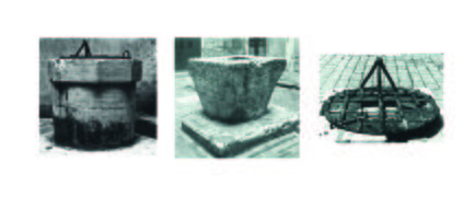
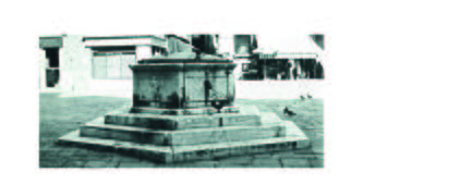
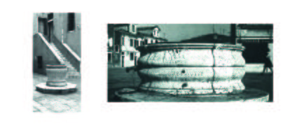
The following illustrations come from the book ''Vere Da Pozzo Di Venezia'', Alberto Rizzi, La Stamperia Di Venezia Editrice, 1981. Rizzi already identified typologies and this project focuses on the first three, discarding the one with sculptures. These typologies can now be modelled semi-automatically by using Rhino Grasshopper and implementing a dimension extraction script and a procedural modelling script. | |||
<gallery mode="packed"> | |||
Image:well-heads-typo-01.jpg| Typologies as described in the book | |||
Image:well-heads-typo-02.jpg| Venetian campo | |||
Image:well-heads-typo-03.jpg| Round only | |||
Image:well-heads-typo-04.jpg| Round to polygonal with sculpted edges | |||
Image:well-heads-typo-05.jpg| Round to polygonal with arches | |||
Image:well-heads-typo-06.jpg| Special complex | |||
Image:well-heads-typo-07.jpg| Special simple | |||
Image:well-heads-typo-08.jpg| Large polygonal | |||
Image:well-heads-typo-09.jpg| Large round | |||
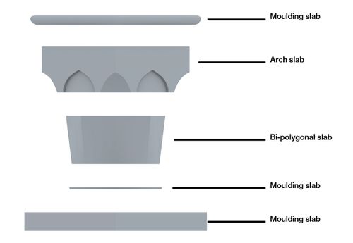
</gallery> | </gallery> | ||
===Approach to modelling well-heads=== | |||
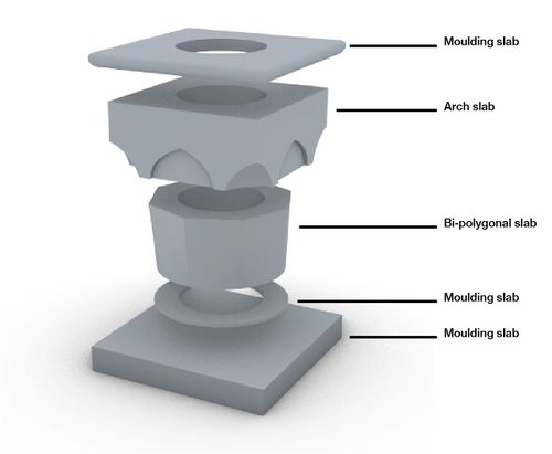
The idea behind a procedural model is to provide some basic geometrical properties and use them to reconstruct a 3D model. In our case, each well-head is split into slabs with different profiles. When stacked together, this looks like a well-head. The challenge is thus to use the photographs to extract the height, radius, and profile of each slab. Then create a script to model the same slabs in 3D and stack them back together. The model includes the possibility to model the three typologies and in this case, it involves modeling three slabs. | |||
===Extract well-heads dimensions=== | |||
The dimension extraction goes as follows. The image below serves as a guiding example. | |||
# Input the height of the well-head found in the book | |||
# Trace a line along the well-head diameter, this set the centre. | |||
# Place points between each slab | |||
# Export a JSON file | |||
# Fine-tune the JSON file. It is ready to be used as input for the script model. | |||
The JSON file describes the polygonal shape and its dimension for both base and top of each slab, however the same value for both is gathered through the placement of points. This is make on purpose, to fasten the process. Any additional change can be done in the fine-tuning of the JSON file when it has been imported into the modelling script. In the modelling script, the operator compares its model with the photograph and adjusts it for the best matching. | |||
{| class="wikitable" style="margin: 1em auto 1em auto;" | |||
| [[File:slabs-types-05.jpg|none|thumb|1200px| Procedure to extract the dimension and export then as JSON]] | |||
|} | |||
===Procedural modelling of well-heads=== | |||
The modelling procedure goes as follows. The images below serve as illustrative examples. | |||
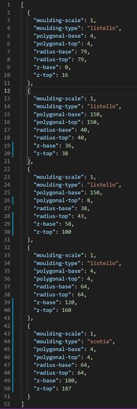
# Read a JSON file with dimensions for each slab. Each slab contains the moulding type, the base radius, the top radius, the base polygon, the top polygon, the base height, the top height, and an horizontal scaling factor (=1). | |||
# Generate each slab according to the JSON file. Stack them together | |||
# Fine tune the parameters for the arch slab: the diameter of arches on the sides and in the corners are setup manually by comparison between the photo and the model. This manual approach provide better accuracy. | |||
# Optionally adjust the parameters for cutting arcs out of the slabs | |||
# Export the 3D model and a rendered picture. | |||
===Slabs modelling=== | |||
The grasshopper script handles three types of slabs: moulding, arch and bi-polygonal, and provides a wide range of tuning parameters. The following images give an overall idea of the possibilities. | |||
{| class="wikitable" style="margin: 1em auto 1em auto;" | |||
| [[File:JSON-well.jpg|none|thumb|200px| JSON file representing the slabs of the imaginary well-head]] | |||
| [[File:slabs-types-01.jpg|none|thumb|500px| Imaginary well-head with all slab's typologies]] | |||
| [[File:slabs-types-02.jpg|none|thumb|500px| Side view]] | |||
|} | |||
'''Arcs on slabs ''' | |||
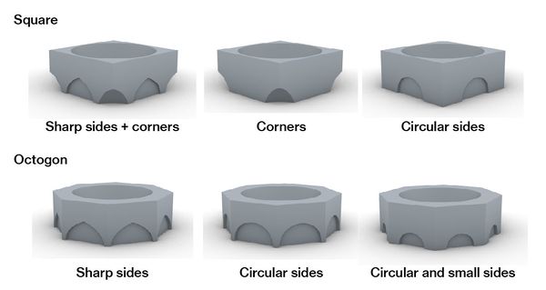
The arcs are obtained through the boolean operation ''difference''. Spheres, cylinders of solids extruded from arc curves are places at the corners and/or sides of a slab in order to remove its volume from the slab. This is an array of shapes repeated along the corners or in the middle of the sides of a polygon that has the same number of sides of the slab to cut. | |||
The parameters that can be customed in the Grasshopper tool are: | |||
* Whether to cut from the corners, the sides or both; | |||
* The shape of the polygon rail, usually the same of the slab; | |||
* The diameter and height of the rail; | |||
* The dimension of the array element: the diameter when it is a sphere, the width and the depth of the cut when it is a cylinder or and extruded arc. | |||
The images below provide an illustrative example. | |||
'''Bi-polygonal slabs''' | |||
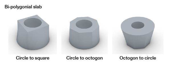
We refers to Bi-polygonal slab when the polygonal shape or the radius of a slab basis is different from the top one. In this case the slab profile is approximate by a planar surface that connects the two different shapes. When both are the same instead we have mouldings. | |||
{| class="wikitable" style="margin: 1em auto 1em auto;" | |||
| [[File:slabs-types-03.jpg|none|thumb|600px| Arch slabs profiles]] | |||
| [[File:slabs-types-04.jpg|none|thumb|600px| Bi-polygonal slabs profiles]] | |||
|} | |||
'''Mouldings''' | |||
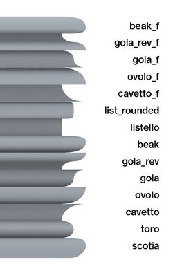
A moulding is a shaped strip with a defined profile with a decorative function. Mouldings help in highlighting the subdivision in parts of an architectural element but also to avoid harsh transitions. In classical architecture they are well defined and formalized, and we notice common trends also in wells profiles. If we consider wells as a stack of slabs indeed we can associate each slab with a specific moulding. | |||
The basis of moulding modelling is the profile. It can be described as a Bezier curve and in this case in particular as two joint segments of a Bezier curve. In this way we can model the most common types of profiles by defining: | |||
* 3 points part of the curve (the starting, middle and ending point) | |||
* 3 control points (displayed as vectors in the figure below) | |||
The resulting curve then is extruded along the perimeter of the slab to get a slab with a moulded contour. | |||
{| class="wikitable" style="margin: 1em auto 1em auto;" | |||
| [[File:mouldings_exemples.jpg|none|thumb|950px| Examples of mouldings defined by a Bezier curve]] | |||
| [[File:mouldings_cheatsheet.jpg|thumb|250px| Moulding slabs profiles]] | |||
|} | |||
===Localize well-heads=== | |||
[[File:loc_extractor_tool.png |thumb| Identified well with IDs]] | |||
We gathered information about the position of the well-heads both in the book and [http://cigno.atlantedellalaguna.it/maps/47/view in this source]. | |||
* In the book there are some sketchy maps with approximative wells location, as well as their ''sestriere'' or district, the ''parrocchia'' or parish and the specific square or courtyard of belongings. | |||
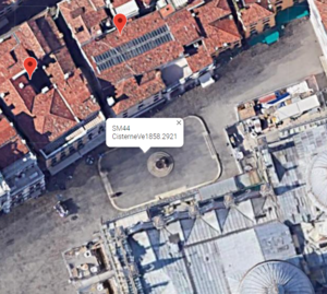
* From the other resource instead we got a GEOjson file with the coordinates of all well-heads recorded in 1857-1858. Most of them are no more there, they don't exist anymore or have been moved somewhere else. We extracted only the ones present in the book thanks to a simple HTML page embedding the Google Maps API and JavaScript code to retrieve the ID of the clicked well in the map. | |||
By comparing these data with the ones from the book we where able to find their actual location. | |||
===JSON catalogue=== | |||
Indexes, IDs and location coordinates have been used to create an already-filled catalogue to reference all the available material in one common place. We took advantage Jupyter Notebook and Python to manage json data. For each well-head we stored its index, ID, coordinates, district, parish, square name, century built, materials, height, diameter and/or side length, 3D model, model rendering, preservation status and pictures page number in the book. | |||
== Results == | == Results == | ||
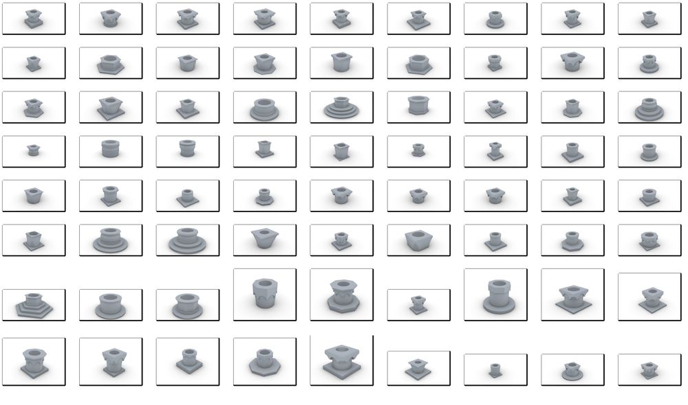
== Future | The main results of the project are listed below and listed on [https://github.com/CheminDavide/3DVeniceWells GitHub]. The following image is a compilation of the 72 3D-modeled well-heads during the project over a total of 230 listed in the book. Each well-head takes approximately 15 minutes. It is estimated that 40 hours is required to model the remaining well-heads. Here is a summary of the results: | ||
* 210 scanned images from the ''Vere da Pozzo'' book. | |||
* 72 digitized well-heads in 3D model as .fbx files. | |||
* 72 related rendered images of the 3D models. | |||
* 72 associated JSON files with the dimensions of each well-head. | |||
* A comprehensive catalog with reference to each well-heads. | |||
{| class="wikitable" style="margin: 1em auto 1em auto;" | |||
| [[File:all-well-heads.jpg|none|thumb|1000px| Compilation of the 72 3D-model of well-heads]] | |||
|} | |||
== Limitations == | |||
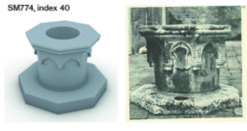
The images below provide a visual comparison between the photographs of the well-heads and the actual 3D-modeled versions. The photograph shown next to the well is the one used to extract all the information to build the geometry of the model. Only the height comes as additional information. The results demonstrate that the typologies of well-heads can be conceptually represented by using a procedural modeling approach. The overall shapes and style can be extracted using grasshopper, stored into JSON files, and then modeled in 3D. A slab decomposition of the well with mouldings, arches and bi-polygonal can address the need to represent a Venetian well-head. | |||
Even if some well-heads are accurate representations, and some are less. The fidelity of the modelization depends on the functionalities of the grasshopper script to extract the information and to model. | |||
Here are some important design limitations to work on: | |||
* Details such as material, surface quality, aging are not modeled. The image ''result 5'' is an illustrative example. | |||
* Details such as sculptures and asymmetrical elements are not modeled. The image ''result 2'' provides an example. | |||
* Some elements included on the photographs such as leaves, the steel cover are lacking in the models. | |||
* Vertical non-standard elements that are not modelable in the grasshopper script are excluded from the model. ''Result 1'' provides an illustrative example with the pillars on the corners. | |||
* The grasshopper modeling script uses a combination of slabs stacked vertically. The slabs in the model come as standard shapes and thus limit the personalization of slabs. For example, the image ''result 10'' demonstrates that regular patterns on the slabs are not present on the model. | |||
* The height of the model may be wrong. The height indicated in the book may include the slab on which the well-head rests or not. The information is lacking. | |||
* During the dimension extraction, the perspective of the photograph brings additional tolerance issues and distorts the real dimensions. The model is then corrected manually to adjust for shape coherence. | |||
* During the dimension extraction, shading due to sunlight on the well-heads provides additional imprecision for the placement of dimension extracting points | |||
* The semi-automated or semi-manual digitization process is time-intensive in human work. When more images of well-heads are available, other technics can be implemented to reduce the human work quantity required. | |||
{| class="wikitable" style="margin: 1em auto 1em auto;" | |||
| [[File:results-01.jpg|none|thumb|500px| Result 1]] | |||
| [[File:results-02.jpg|none|thumb|500px| Result 2]] | |||
|} | |||
{| class="wikitable" style="margin: 1em auto 1em auto;" | |||
| [[File:results-03.jpg|none|thumb|500px| Result 3]] | |||
| [[File:results-04.jpg|none|thumb|500px| Result 4]] | |||
|} | |||
{| class="wikitable" style="margin: 1em auto 1em auto;" | |||
| [[File:results-05.jpg|none|thumb|500px| Result 5]] | |||
| [[File:results-06.jpg|none|thumb|500px| Result 6]] | |||
|} | |||
{| class="wikitable" style="margin: 1em auto 1em auto;" | |||
| [[File:results-07.jpg|none|thumb|500px| Result 7]] | |||
| [[File:results-08.jpg|none|thumb|500px| Result 8]] | |||
|} | |||
{| class="wikitable" style="margin: 1em auto 1em auto;" | |||
| [[File:results-09.jpg|none|thumb|500px| Result 9]] | |||
| [[File:results-10.jpg|none|thumb|500px| Result 10]] | |||
|} | |||
== Future Work == | |||
The list below discusses about the points of further improvement and the next steps: | |||
* Continue the modeling of the remaining well-heads. | |||
* Develop a new grasshopper script to model elements present at the corner of well-heads like spirals on image ''result 2'' or pillars on image ''result 1''. | |||
* Improve the grasshopper script for dimension extraction to accommodate the perspective of the photographs. | |||
* Develop a grasshopper script for dimension extraction that uses Bezier's curves to get an improved well-head profile. | |||
* The concept of using slab decomposition can be expanded to other architectural elements such as columns or walls. | |||
==Credits== | |||
* Project developed by Davide Chemin davide.chemin(a)epfl.ch and Loïc Rochat loic.rochat(a)epfl.ch | |||
* Professor: Frédéric Kaplan | |||
* Supervisors: Paul Guhennec, Beatrice Vaienti and Didier Dupertuis | |||
* Class: Foundation of Digital Humanities, EPFL | |||
* Date: autumn 2021 | |||
Latest revision as of 15:37, 7 April 2022
Motivation
Venice is one of the cities in Europe with the richest and largest number of well-heads, locally known as Vere da Pozzo. This term refers to the stone structure surrounding the pipe of a well with a protective function. Across history, the role of wells for Venice has always been crucial, in first place to assure drinking water for citizens. Although on water, the city needed wells to store unsalted water. They were placed most of the time in the middle of a square or a private courtyard to collect rainwater and filter it in the ground. In times of drought, they were filled with fresh water from the nearby Brenta river.
Over time, the need and societal use of wells evolve along society. Once more than 6000 across all Venice, it is today estimated that more than 2300 well-heads are spread across the city. To better understand these changes, the goal of this digital humanities project is to digitize well-heads and thus provide additional material to upgrade the Venice 1808 digital Cadastre in development at the EPFL DH lab.
The project uses the book Vere da Pozzo by Alberto Rizzi with circa 250 references of well-heads in the wider Venice islands. It lists photos, description of conservation, periods of construction, material, and overall dimensions. It is complemented with the GPS locations of well-heads in Venice available here.
The material available limits the level of detail one can extract through digitization. Some wells are badly preserved and most of the time, only one photograph is provided. Pictures of well-heads are similar to a profile point of view but vary case by case. However, the material is good enough to give clear indications of the overall shape and the style adopted. The architectural styles of well-heads are thus the key elements to be successfully digitized in this project. It takes the form of 3D models semi-automatically generated out-of-the-book pictures. The reader could expect to recognize arches, geometrical symmetries, overall size, and moulding styles as differentiating elements of Venetian well-heads. Detailed sculptures won't be reproduced.
Outcome and deliverables
The deliverables are available on GitHub. Here are the main elements:
The tools:
- Rhino Grasshopper script to model well-heads with arches, mouldings, and varying polygonal slabs.
- Rhino Grasshopper script to extract the dimensions and store them into a JSON file.
- Localization tool to match all the known GPS location of well heads with the ones of the book.
- A Jupyter Notebook with python code to create the json catalogue file already filled with the available information (index, IDs and coordinates).
The results:
- Scanned images of Vere da Pozzo by Alberto Ricci.
- Digitized well-heads in 3D model as .fbx files.
- Related rendered images of the 3D models.
- Associated JSON files with the dimensions of each well-head.
- A comprehensive catalogue with reference to each well-heads with information like location, district, date, material, dimensions and links to 3D models and pictures.
Project Plan
The project is separated in three main goals: identify the historical document to use, develop the digitization methods and finally perform the digitization. The following table provides the project plan.
| Date | Task | Completion |
|---|---|---|
| By Week 3 |
|
✓ |
| By Week 4 |
|
✓ |
| By Week 5 |
|
✓ |
| By Week 6 |
|
✓ |
| By Week 7 |
|
✓ |
| By Week 8 |
|
✓ |
| By Week 9 |
|
✓ |
| By Week 10 |
|
✓ |
| By Week 11 |
|
✓ |
| By Week 12 |
|
✓ |
| By Week 13 |
|
✓ |
| By Week 14 |
|
✓ |
Methodology
The Venetian wells are magnificent, feature beautiful sculptures and pose a great challenge to digitize in 3D. Some project model buildings with photogrammetric technics. The availability of aerial videos provides multiple viewing angles and offer thus the possibility to use computer intensive algorithms and a mostly automated approach. This is not the case with well-heads, and it, therefore, asks us to adopt a different strategy.
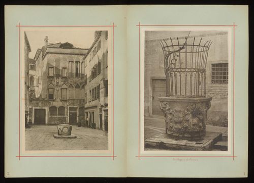
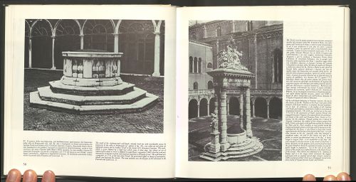
Few documents provide a comprehensive and systematic approach to the reproduction of well-heads. One of them is Raccolta delle vere da pozzo by Ferd. Ongania published in 1889. It is the oldest and first one to reproduce well-heads with photography. It looks like a great photo album: quality photographs with names and places. The photo are adequate for modelling, however, they lack detailed metadata such as height to calibrate the 3d models. That's why the project selected a more recent catalogue, Alberto Rizzi's book. It features a smaller number of well heads but with the metadata required. Below, two images of Ongania and Rizzi's books.
Typologies and procedural modelling
To model a well-head, one ideally needs to get a perspective of all viewing angles. In this case, only one picture from the side is given. The modelization then takes into consideration additional information and compensates for this information asymmetry. The well-head is symmetric and features specific architectural styles. The goal is to identify the most basic typologies of wells with basic geometric shapes and use them to model a simple shape of each well with Rhino Grasshopper.
Common typologies of wells in Venice:
- Base with circular, square, hexagonal, octagonal, decagonal (10), dodecagonal (12) shapes.
- Top with circular, square, hexagonal, octagonal, decagonal (10), dodecagonal (12) shapes.
- Edges are either sharp or embedding a sculpture that cut them.
- Well-heads rest on a slab with one, two or three steps.
- Top 15-30cm of the well either have flanges with square or circular profiles or arcades
Additionally, one notes that architectural styles and typologies also refer to the historical periods. This approach is thus relevant from a historical point of view, and the later digital historian will be able to use 3D models such as the ones developed in this project. Below is a table with the classification by stylistic appearance and historical period of well-heads:
| Type | Period | Features |
|---|---|---|
| Archeological | Greek and Roman | Rough, made from column shafts, altars, memorial stones, cinerary urns and other pieces. |
| Carolingian | VIII-X centuries | Cubic, decorated with symbols of Christian art |
| Venetian-Byzantine | XI-XIII centuries | Free-standing cylinder decorated with pillars or columns |
| Gothic | XIV-XV centuries | Like capitals of columns or pillars, with square frame |
| Traditional | from 1300 | Cylindrical shaft with small arches in the corners |
| Lombardesque | late XV-early XVI centuries | Modelled like columns capitals |
| Renaissance | mid XV-mid XVI centuries | Polygonal shape with figures in the lateral boxes |
| Baroques | XVI-XVIII centuries | Double swelling in the middle |
| Neoclassical | XVIII-XIX centuries | Very simple cylindrical structure |
The following illustrations come from the book Vere Da Pozzo Di Venezia, Alberto Rizzi, La Stamperia Di Venezia Editrice, 1981. Rizzi already identified typologies and this project focuses on the first three, discarding the one with sculptures. These typologies can now be modelled semi-automatically by using Rhino Grasshopper and implementing a dimension extraction script and a procedural modelling script.
Approach to modelling well-heads
The idea behind a procedural model is to provide some basic geometrical properties and use them to reconstruct a 3D model. In our case, each well-head is split into slabs with different profiles. When stacked together, this looks like a well-head. The challenge is thus to use the photographs to extract the height, radius, and profile of each slab. Then create a script to model the same slabs in 3D and stack them back together. The model includes the possibility to model the three typologies and in this case, it involves modeling three slabs.
Extract well-heads dimensions
The dimension extraction goes as follows. The image below serves as a guiding example.
- Input the height of the well-head found in the book
- Trace a line along the well-head diameter, this set the centre.
- Place points between each slab
- Export a JSON file
- Fine-tune the JSON file. It is ready to be used as input for the script model.
The JSON file describes the polygonal shape and its dimension for both base and top of each slab, however the same value for both is gathered through the placement of points. This is make on purpose, to fasten the process. Any additional change can be done in the fine-tuning of the JSON file when it has been imported into the modelling script. In the modelling script, the operator compares its model with the photograph and adjusts it for the best matching.
Procedural modelling of well-heads
The modelling procedure goes as follows. The images below serve as illustrative examples.
- Read a JSON file with dimensions for each slab. Each slab contains the moulding type, the base radius, the top radius, the base polygon, the top polygon, the base height, the top height, and an horizontal scaling factor (=1).
- Generate each slab according to the JSON file. Stack them together
- Fine tune the parameters for the arch slab: the diameter of arches on the sides and in the corners are setup manually by comparison between the photo and the model. This manual approach provide better accuracy.
- Optionally adjust the parameters for cutting arcs out of the slabs
- Export the 3D model and a rendered picture.
Slabs modelling
The grasshopper script handles three types of slabs: moulding, arch and bi-polygonal, and provides a wide range of tuning parameters. The following images give an overall idea of the possibilities.
Arcs on slabs
The arcs are obtained through the boolean operation difference. Spheres, cylinders of solids extruded from arc curves are places at the corners and/or sides of a slab in order to remove its volume from the slab. This is an array of shapes repeated along the corners or in the middle of the sides of a polygon that has the same number of sides of the slab to cut. The parameters that can be customed in the Grasshopper tool are:
- Whether to cut from the corners, the sides or both;
- The shape of the polygon rail, usually the same of the slab;
- The diameter and height of the rail;
- The dimension of the array element: the diameter when it is a sphere, the width and the depth of the cut when it is a cylinder or and extruded arc.
The images below provide an illustrative example.
Bi-polygonal slabs
We refers to Bi-polygonal slab when the polygonal shape or the radius of a slab basis is different from the top one. In this case the slab profile is approximate by a planar surface that connects the two different shapes. When both are the same instead we have mouldings.
Mouldings
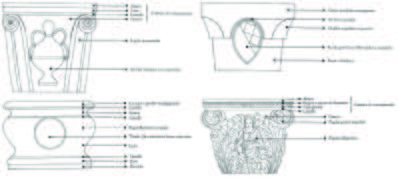
A moulding is a shaped strip with a defined profile with a decorative function. Mouldings help in highlighting the subdivision in parts of an architectural element but also to avoid harsh transitions. In classical architecture they are well defined and formalized, and we notice common trends also in wells profiles. If we consider wells as a stack of slabs indeed we can associate each slab with a specific moulding. The basis of moulding modelling is the profile. It can be described as a Bezier curve and in this case in particular as two joint segments of a Bezier curve. In this way we can model the most common types of profiles by defining:
- 3 points part of the curve (the starting, middle and ending point)
- 3 control points (displayed as vectors in the figure below)
The resulting curve then is extruded along the perimeter of the slab to get a slab with a moulded contour.
Localize well-heads
We gathered information about the position of the well-heads both in the book and in this source.
- In the book there are some sketchy maps with approximative wells location, as well as their sestriere or district, the parrocchia or parish and the specific square or courtyard of belongings.
- From the other resource instead we got a GEOjson file with the coordinates of all well-heads recorded in 1857-1858. Most of them are no more there, they don't exist anymore or have been moved somewhere else. We extracted only the ones present in the book thanks to a simple HTML page embedding the Google Maps API and JavaScript code to retrieve the ID of the clicked well in the map.
By comparing these data with the ones from the book we where able to find their actual location.
JSON catalogue
Indexes, IDs and location coordinates have been used to create an already-filled catalogue to reference all the available material in one common place. We took advantage Jupyter Notebook and Python to manage json data. For each well-head we stored its index, ID, coordinates, district, parish, square name, century built, materials, height, diameter and/or side length, 3D model, model rendering, preservation status and pictures page number in the book.
Results
The main results of the project are listed below and listed on GitHub. The following image is a compilation of the 72 3D-modeled well-heads during the project over a total of 230 listed in the book. Each well-head takes approximately 15 minutes. It is estimated that 40 hours is required to model the remaining well-heads. Here is a summary of the results:
- 210 scanned images from the Vere da Pozzo book.
- 72 digitized well-heads in 3D model as .fbx files.
- 72 related rendered images of the 3D models.
- 72 associated JSON files with the dimensions of each well-head.
- A comprehensive catalog with reference to each well-heads.
Limitations
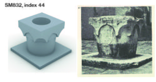
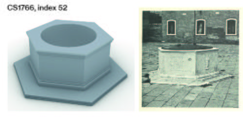
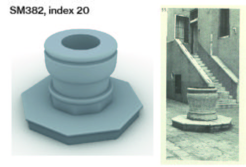
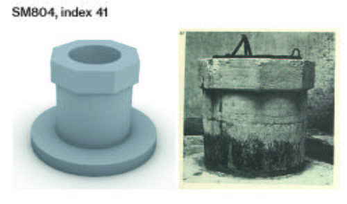
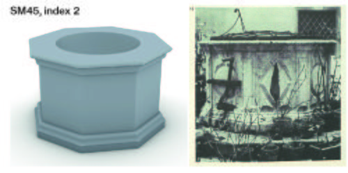
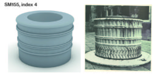
The images below provide a visual comparison between the photographs of the well-heads and the actual 3D-modeled versions. The photograph shown next to the well is the one used to extract all the information to build the geometry of the model. Only the height comes as additional information. The results demonstrate that the typologies of well-heads can be conceptually represented by using a procedural modeling approach. The overall shapes and style can be extracted using grasshopper, stored into JSON files, and then modeled in 3D. A slab decomposition of the well with mouldings, arches and bi-polygonal can address the need to represent a Venetian well-head.
Even if some well-heads are accurate representations, and some are less. The fidelity of the modelization depends on the functionalities of the grasshopper script to extract the information and to model.
Here are some important design limitations to work on:
- Details such as material, surface quality, aging are not modeled. The image result 5 is an illustrative example.
- Details such as sculptures and asymmetrical elements are not modeled. The image result 2 provides an example.
- Some elements included on the photographs such as leaves, the steel cover are lacking in the models.
- Vertical non-standard elements that are not modelable in the grasshopper script are excluded from the model. Result 1 provides an illustrative example with the pillars on the corners.
- The grasshopper modeling script uses a combination of slabs stacked vertically. The slabs in the model come as standard shapes and thus limit the personalization of slabs. For example, the image result 10 demonstrates that regular patterns on the slabs are not present on the model.
- The height of the model may be wrong. The height indicated in the book may include the slab on which the well-head rests or not. The information is lacking.
- During the dimension extraction, the perspective of the photograph brings additional tolerance issues and distorts the real dimensions. The model is then corrected manually to adjust for shape coherence.
- During the dimension extraction, shading due to sunlight on the well-heads provides additional imprecision for the placement of dimension extracting points
- The semi-automated or semi-manual digitization process is time-intensive in human work. When more images of well-heads are available, other technics can be implemented to reduce the human work quantity required.
Future Work
The list below discusses about the points of further improvement and the next steps:
- Continue the modeling of the remaining well-heads.
- Develop a new grasshopper script to model elements present at the corner of well-heads like spirals on image result 2 or pillars on image result 1.
- Improve the grasshopper script for dimension extraction to accommodate the perspective of the photographs.
- Develop a grasshopper script for dimension extraction that uses Bezier's curves to get an improved well-head profile.
- The concept of using slab decomposition can be expanded to other architectural elements such as columns or walls.
Credits
- Project developed by Davide Chemin davide.chemin(a)epfl.ch and Loïc Rochat loic.rochat(a)epfl.ch
- Professor: Frédéric Kaplan
- Supervisors: Paul Guhennec, Beatrice Vaienti and Didier Dupertuis
- Class: Foundation of Digital Humanities, EPFL
- Date: autumn 2021
