Procedural modeling of Muqarnas: Difference between revisions
| (88 intermediate revisions by 2 users not shown) | |||
| Line 27: | Line 27: | ||
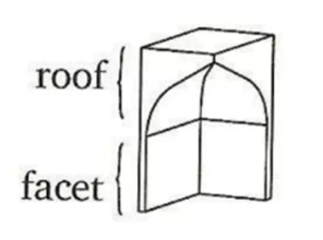
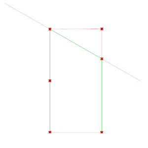
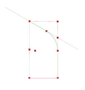
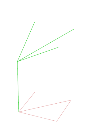
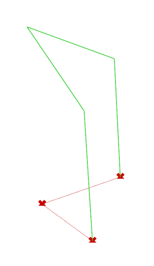
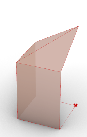
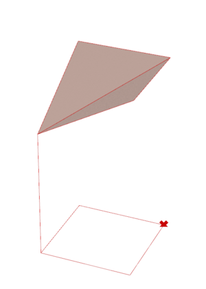
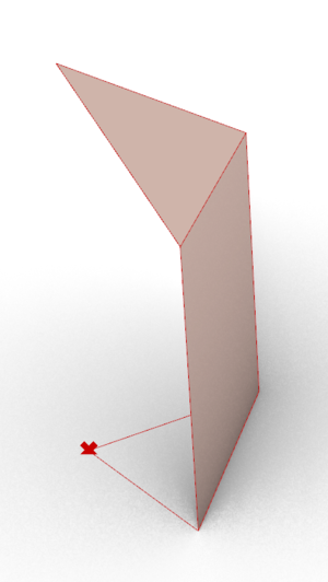
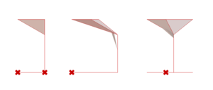
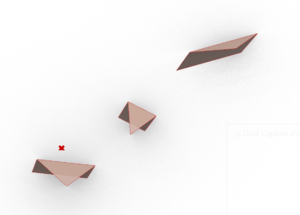
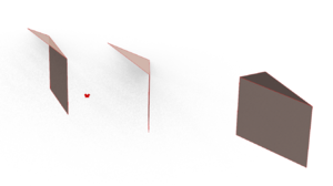
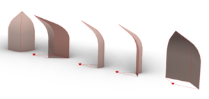
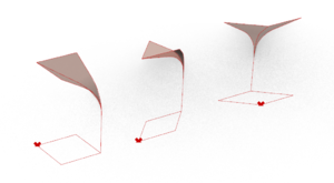
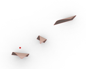
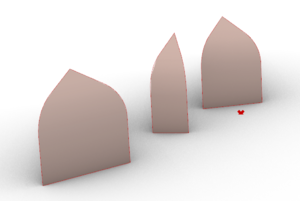
“A muqarnas is a stair-like ceiling that has facets and a surface. Each facet intersects with its adjacent either on a right angle or half a right angle or the sum of one and a half right angles, or others. The two facets can be thought of as perpendicular to a plane parallel to the horizon. Built over these two facets is a plane not parallel to the horizon, or two planes, or two curved surfaces, which are the ceiling of the facets. The two facets along with their ceiling are called a cell. Adjacent cells with bases on the same plane parallel to the horizon are called a tier. The length of the base of the largest facet is called the module of the muqarnas.” | “A muqarnas is a stair-like ceiling that has facets and a surface. Each facet intersects with its adjacent either on a right angle or half a right angle or the sum of one and a half right angles, or others. The two facets can be thought of as perpendicular to a plane parallel to the horizon. Built over these two facets is a plane not parallel to the horizon, or two planes, or two curved surfaces, which are the ceiling of the facets. The two facets along with their ceiling are called a cell. Adjacent cells with bases on the same plane parallel to the horizon are called a tier. The length of the base of the largest facet is called the module of the muqarnas.” | ||
{| class="wikitable" style="margin: 1em auto 1em auto;" | |||
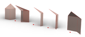
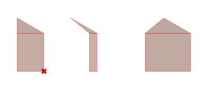
| [[File:facet.png|thumb| Facet and roof of a Muqarnas cell]] | |||
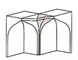
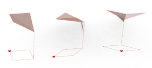
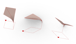
| [[File:intermediate.png|thumb| Intermediate element connecting two adjacent cells]] | |||
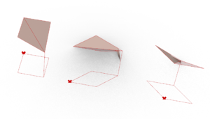
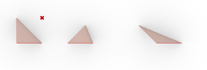
| [[File:tiers.png|none|thumb| Tiers of a Muqarnas]] | |||
|} | |||
'''Facet:''' vertical side of a unit | '''Facet:''' vertical side of a unit | ||
| Line 41: | Line 46: | ||
=== Muqarnas elements === | === Muqarnas elements === | ||
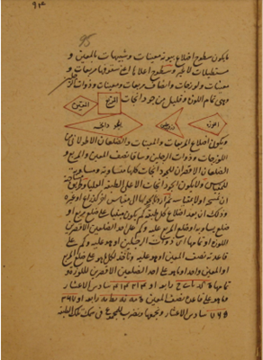
Al Kashi describes five types of elements. The two main ones are the square and the rhombus, whose sides are equal to the module defined. Other elements mentioned are the Almond, Biped and Barley-Kernel. | Al Kashi describes five types of elements. The two main ones are the square and the rhombus, whose sides are equal to the module defined. Other elements mentioned are the Almond, Biped and Barley-Kernel. | ||
=== Muqarnas Types === | === Muqarnas Types === | ||
| Line 56: | Line 59: | ||
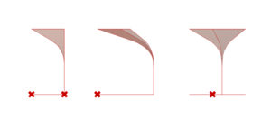
'''4. Shirazi-style muqarnas:''' like curved muqarnas but with a larger variety of elements | '''4. Shirazi-style muqarnas:''' like curved muqarnas but with a larger variety of elements | ||
{| class="wikitable" style="margin: 1em auto 1em auto;" | |||
| [[File:elements.png|thumb| Elements defined by Al Kashi]] | |||
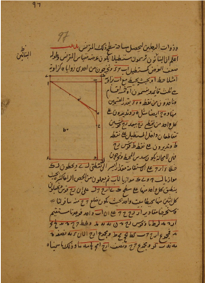
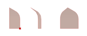
| [[File:curvature.png|thumb| Curved Muqarnas construction]] | |||
|} | |||
==Methodology== | ==Methodology== | ||
===Create the shapes in 2D=== | ===Create the shapes in 2D=== | ||
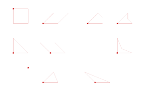
[[File:Shapes_with_origins.PNG|thumb|All the base shapes with the origin highlighted. Top row, left to right: Square, Rhombus-45, Almond, Small Biped. Middle row, left to right: half-square, Rhombus-135, Large Biped. Bottom row, left to right: half-rhombus-45, half-rhombus-135]] | |||
The first elements we constructed on Grasshopper are the base shapes found in the floorplans of muqarnas. Each of these shapes has at least one segment with a length equal to the module: we will call it the Module Segment. | |||
Dold's research paper (see section 8.1) on Al-Kashi’s book explains the geometrical steps to construct them. However, we also need to parametrize our shape builders – that is, allow them to produce a shape from any set of input points in the XY plane and any module length while still respecting the geometrical rules of construction. | |||
To do so, we implement each shape using a three-point system: | |||
- The origin: one vertex of the shape, it always corresponds to one end of the Module Segment. The origin is often the first vertex mentioned in the construction process and from which the other vertices of the shape are built. | |||
- The direction point: a point which determines in which direction from the origin the Module Segment will be built. It does not correspond to any vertex of the shape, unless placed one module away from the origin. | |||
- The symmetry point: this point is placed on either side of the vector created by the origin and the direction point and determines on which side of the Module Segment the rest of the shape will be built. It does not correspond to any vertex of the shape. | |||
Each shape builder takes these three points and the module length as inputs and returns as outputs | |||
- The shape (as a curve), | |||
- A list of its vertices, ordered clockwise from the origin, | |||
- Its diagonal starting from the origin, | |||
- The module. | |||
With this system, we can easily build shapes tessellating next to each other, by connecting one shape’s vertices to another shape builder. | |||
===Transform the shapes in 3D=== | ===Transform the shapes in 3D=== | ||
==== | |||
==== | The next step is to obtain the 3D elements from the base shapes. There are 3 types of elements: a cell for a full-shape, an intermediate element, and a cell for a half-shape. | ||
====The Arc from the Method of Masons==== | |||
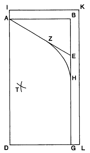
We build the arc according to which the base shape will be projected in order to form a cell. The construction process of this arc is detailed in Dold's research paper (see section 8.1). With the first few steps of the process, we create the Simple Arc. | |||
The rest of the process allows us to create the Curved Arc. | |||
{| class="wikitable" style="margin: 1em auto 1em auto;" | |||
| [[File:schema_arc.PNG|thumb|The schema for the construction of the Arc in Dold's paper]] | |||
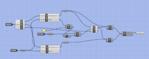
| [[File:simple_arc_circuit.PNG|thumb|Circuit for the Simple Arc in Grasshopper]] [[File:simple_arc.PNG|thumb|Construction of the Simple Arc in Grasshopper]] | |||
| [[File:ca.PNG|thumb|Circuit for the Curved Arc in Grasshopper]] [[File:curved_arc.PNG|thumb|Construction of the Curved Arc in Grasshopper]] | |||
|} | |||
====The 3D Projection==== | |||
Next, this is how we construct a Cell for a full-shape. | |||
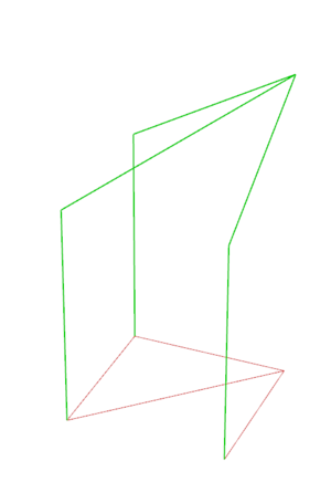
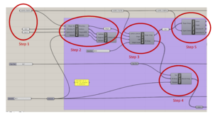
- Step 1: using the ordered list of vertices, we select two adjacent module segments on the shape, and construct instances of the same Arc (simple or curved) along them. These two arcs are positioned such that they start on two different points and end (at their highest point) over the origin of the shape. Then, we project this arc onto the diagonal of the shape. | |||
- Step 2: we simply use a loft on these Arcs in order to create the cell's surface. | |||
{| class="wikitable" style="margin: 1em auto 1em auto;" | |||
| [[File:cell_circuit.PNG|thumb|The grasshopper circuit for a cell. Circuits for the intermediate element and half-cell are nearly identical]] | |||
| [[File:cell_square_in_progress.PNG|thumb|Step 1. The Arcs along the Module Segments and the Arc's projection along the diagonal are highlighted.]] [[File:Int_square_progress.PNG|thumb|Step 1.]] [[File:Half_square_cell_progress.PNG|thumb|Step 1.]] | |||
| [[File:cell_square.PNG|thumb|Step 2. The Simple Cell for a square]] [[File:Int_square.PNG|thumb|Step 1.]] [[File:Half_square_cell.PNG|thumb|Step 1.]] | |||
|} | |||
The process to create a cell for a half-shape is the same, except there is no need to project the arc onto a diagonal. | |||
The process to create an intermediate element is also similar to that of the full-shape cell, save for the fact that we select different segments along which to construct the arcs. In the case of an intermediary element, the arcs are positioned to both start from the point opposite to the origin. | |||
===Create the 2D plan and the 3D volume=== | ===Create the 2D plan and the 3D volume=== | ||
[[File:flcs.PNG|thumb|The circuit for the first tier]] | |||
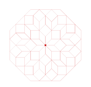
[[File:plan_with_super_center.PNG|thumb|The 2D Plan of our main model, with the Super Center highlighted]] | |||
The 2D plan and the 3D volume of the Muqarnas are created in parallel. The same process is used for each tier, with only the base shape and type of 3D element (cell or intermediate) changing. | |||
- Step 1: for the first/top tier, we create three points anywhere on the canvas. One of these will be the highest point of the model, and will be used in every tier's construction: we call it the Super Center. | |||
- Step 2: we select a shape and build it with the help of our three points. We also create its corresponding 3D element, alternating at each layer between a cell and an intermediate element (the top tier is always composed of cells) | |||
- Step 3: we create two polar arrays (one for shapes, one for cells) around the Super Center, so that the elements are adjacent without overlapping. | |||
- Step 4: we move the array of 3D elements along the Z-axis to account for the change in tier. We subtract 1 to the previous tier height if the tier we are building is made of intermediate elements, and we keep the previous tier's height if the current tier is made of cells. | |||
- Step 5: using the polar array of 2D shapes, we create a curve corresponding to the outer boundary of the 2D plan. Then, using distance calculations, we extract three points from this boundary: these points form an angle A in which we can build the base shape of the next layer. | |||
We repeat steps 2 to 5 for each tier, until we obtain an angle A measuring 180 degrees or more: in this case, there is no shape that can be built in the angle. | |||
====In practice==== | |||
In practice, there are many more possible combinations than the ones we can obtain by composing each tier with one base shape. For instance, if the angle A is 135 degrees, we can create an array of rhombus-135 cells, but we can also create an array of elements made of three rhombus-45 cells positioned side-by-side. We tested this particular example in a layer of our model, using a polar array of 3 rhombus-45's over an angle of 135 degrees as a base shape. | |||
Tiers obtained with an array of multiple side-by-side shapes add extra difficulties when we want to construct further tiers: in our example, each rhombus of a triple-rhombus element is positioned in a different direction from the Super Center, which makes extracting the points and angles more difficult since the distance from the Super Center to the vertices of each rhombus varies. | |||
== Project Plan == | == Project Plan == | ||
| Line 167: | Line 257: | ||
==Results== | ==Results== | ||
===3D shapes=== | ===3D shapes=== | ||
{|class="wikitable" style="margin: 1em auto 1em auto; text-align:right; font-family:Arial, Helvetica, sans-serif !important;;" | |||
|[[File:c_top.PNG|thumb|Cells from the top. From left to right: square, rhombus-45, rhombus-135, almond, small biped]] | |||
|[[File:c_front.PNG|thumb|Cells from the front]] | |||
|[[File:cp1.PNG|thumb|]] | |||
|[[File:cp2.PNG|thumb|]] | |||
|- | |||
|[[File:i_top.PNG|thumb|Intermediate elements from the top. From left to right: square, rhombus-45, rhombus-135]] | |||
|[[File:i_front.PNG|thumb|Intermediate elements from the front]] | |||
|[[File:ip1.PNG|thumb|]] | |||
|[[File:ip2.PNG|thumb|]] | |||
|- | |||
|[[File:hc_top.PNG|thumb|Half-shape cells from the top. From left to right: half-square, half-rhombus-45, half-rhombus-135]] | |||
|[[File:hc_front.PNG|thumb|Half-shape cells from the front]] | |||
|[[File:hcp1.PNG|thumb|]] | |||
|[[File:hcp2.PNG|thumb|]] | |||
|} | |||
===3D shapes with curve=== | ===3D shapes with curve=== | ||
{|class="wikitable" style="margin: 1em auto 1em auto; text-align:right; font-family:Arial, Helvetica, sans-serif !important;;" | |||
|[[File:cc_top.PNG|thumb|Curved cells from the top. From left to right: square, rhombus-45, rhombus-135, almond, small biped]] | |||
|[[File:cc_front.PNG|thumb|Curved cells from the front]] | |||
|[[File:ccp1.PNG|thumb|]] | |||
|[[File:ccp2.PNG|thumb|]] | |||
|- | |||
|[[File:ci_top.PNG|thumb|Curved intermediate elements from the top. From left to right: square, rhombus-45, rhombus-135]] | |||
|[[File:ci_front.PNG|thumb|Curved intermediate elements from the front]] | |||
|[[File:cip2.PNG|thumb|]] | |||
|[[File:cip1.PNG|thumb|]] | |||
|- | |||
|[[File:chc_top.PNG|thumb|Curved half-shape cells from the top From left to right: half-square, half-rhombus-45, half-rhombus-135]] | |||
|[[File:chc_front.PNG|thumb|Curved half-shape cells from the front]] | |||
|[[File:chcp1.PNG|thumb|]] | |||
|[[File:chcp2.PNG|thumb|]] | |||
|} | |||
===2D Plan for Muqarnas model=== | |||
{|class="wikitable" style="margin: 1em auto 1em auto; text-align:right; font-family:Arial, Helvetica, sans-serif !important;;" | |||
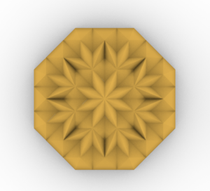
| [[File:plan_with_super_center.PNG|thumb|The plan for our main model. In order from inside, the tiers are: a tier of rhombus-45 cells, a tier of square intermediate elements, a tier of 3-Rhombus cells, a tier of square intermediate elements, and a tier alternating rhombus-135 cells and half-square cells]] | |||
|} | |||
===Simple Muqarnas=== | ===Simple Muqarnas=== | ||
{|class="wikitable" style="margin: 1em auto 1em auto; text-align:right; font-family:Arial, Helvetica, sans-serif !important;;" | |||
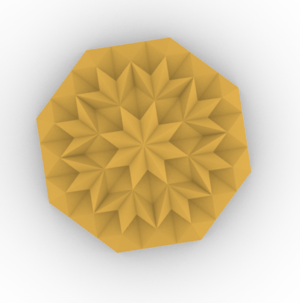
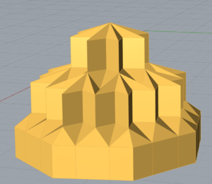
|[[File:muq_top.PNG|thumb|Simple muqarna model from the top]] | |||
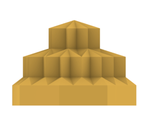
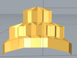
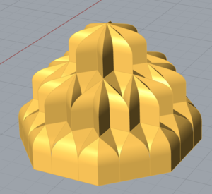
|[[File:muq_front.PNG|thumb|Simple muqarna model from the front]] | |||
|[[File:muqp.PNG|thumb|Simple muqarna model in perspective]] | |||
|[[File:muq_cut.PNG|thumb|Inside of the model]] | |||
|} | |||
===Curved Muqarnas=== | ===Curved Muqarnas=== | ||
{|class="wikitable" style="margin: 1em auto 1em auto; text-align:right; font-family:Arial, Helvetica, sans-serif !important;;" | |||
|[[File:cmuq_top.PNG|thumb|Curved muqarna model from the top]] | |||
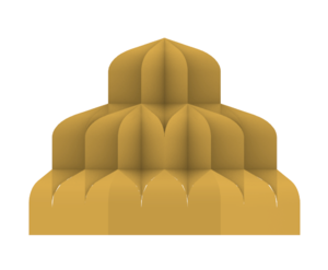
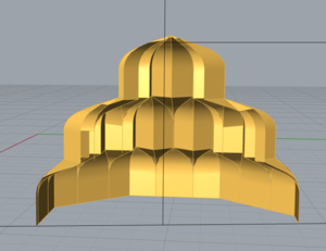
|[[File:cmuq_front.PNG|thumb|Curved muqarna model from the front]] | |||
|[[File:cmuqp.PNG|thumb|Curved muqarna model in perspective]] | |||
|[[File:cmuq_cut.PNG|thumb|Inside of the model]] | |||
|} | |||
{|class="wikitable" style="margin: 1em auto 1em auto; text-align:right; font-family:Arial, Helvetica, sans-serif !important;;" | |||
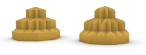
|[[File:Rendered_side_by_side.PNG|thumb|The Simple and Curved models side-by-side]] | |||
|} | |||
==Limitations== | ==Limitations== | ||
Due to time constraints, only one example plan of the simple and curved Muqarnas was implemented on Grasshopper. | |||
The way to input the shapes and add tier levels can become even more parametric: for instance, we could detect the measure of the angle A and retrieve the different options for the base shape of the next tier according to the measure of A. | |||
Another method to construct the plan would be to start from a base shape with a 45 degree angle, multiply it by eight and generate it’s complement that constitutes the intermediary element for the next tier. After that, the shape of the element of the next tier would be determined according to the angle between the two intermediate elements. (For example, a 90 degree angle can be filled with two rhombuses, a square or an almond, etc.). Due to time constraints, we could not implement 2D shapes built as complements to other shapes, nor could we implement the intermediate elements for the almond, small biped and large biped. | |||
We at first tried to implement the Barley-Kernel, another one of the base shapes. However, we realised it would be too difficult to use in an actual Muqarnas model because the length of its diagonal is variable (no one value is specified in the literature we used). | |||
We also encountered some issues with the model as it would sometimes bug depending on the orientation of the base points, or on the length of the module if it was strictly higher than 1: some tiers would disappear or be built in an incorrect direction. | |||
==Future work== | ==Future work== | ||
| Line 181: | Line 344: | ||
==Github Repository== | ==Github Repository== | ||
[https://github.com/mariellad/Procedural-Modeling-of-Muqarnas Procedural Modeling of Muqarnas] | |||
==References== | ==References== | ||
=== Literatures === | === Literatures === | ||
Latest revision as of 22:58, 21 December 2022
Introduction & Motivation
Muqarnas is a type of 3D ornamentation used in Islamic Architecture. This form of ornamentation was first developed during the Abbasid Empire. It is a complex stalactite vaulted structure composed of different units arranged one on top of another and spanning several tiers. The primary purpose of Muqarnas was to create a transition between a circular dome and the square structure beneath it.
This project uses procedural modeling to recreate several types of 3D Muqarnas models based on fixed sets of rules.
The logic followed to recreate 3D muqarnas models is mainly based on the book Miftah al-Hisab, Volume II: Geometry written in 1427 by Jamshid Al Kashi, a 15th century Persian mathematician and astronomer. In this book, Al Kashi tries to simplify complex geometric calculations in a way that lets artisans who do not have a thorough mathematical understanding to efficiently and accurately perform calculations necessary for taking measurements of the structures they are constructing.
The third section of his book On the surface area of the muqarnas contains three key points interesting for our project:
1. Muqarnas Definition
2. Muqarnas elements
3. Muqarnas Types
Muqarnas Definition
In his book, Al Kashi gave the following definition of a Muqarnas:
“A muqarnas is a stair-like ceiling that has facets and a surface. Each facet intersects with its adjacent either on a right angle or half a right angle or the sum of one and a half right angles, or others. The two facets can be thought of as perpendicular to a plane parallel to the horizon. Built over these two facets is a plane not parallel to the horizon, or two planes, or two curved surfaces, which are the ceiling of the facets. The two facets along with their ceiling are called a cell. Adjacent cells with bases on the same plane parallel to the horizon are called a tier. The length of the base of the largest facet is called the module of the muqarnas.”
Facet: vertical side of a unit
Roof: plane not parallel to the horizon, or two planes, or two curved surfaces on top of the facets
Cell: two facets along with their roofs
Intermediate element: surface, or two joint surfaces, connecting the roofs of two adjacent cells
Tier: Adjacent cells with bases on the same plane parallel to the horizon
Module: length of the base of the largest facet
Muqarnas elements
Al Kashi describes five types of elements. The two main ones are the square and the rhombus, whose sides are equal to the module defined. Other elements mentioned are the Almond, Biped and Barley-Kernel.
Muqarnas Types
1. Simple Muqarnas: the ceilings have plane surfaces only
2. Clay-plaster muqarnas: simple muqarnas but the tiers do not have the same height
3. Curved muqarnas: surfaces of the ceilings are curved
4. Shirazi-style muqarnas: like curved muqarnas but with a larger variety of elements
Methodology
Create the shapes in 2D
The first elements we constructed on Grasshopper are the base shapes found in the floorplans of muqarnas. Each of these shapes has at least one segment with a length equal to the module: we will call it the Module Segment.
Dold's research paper (see section 8.1) on Al-Kashi’s book explains the geometrical steps to construct them. However, we also need to parametrize our shape builders – that is, allow them to produce a shape from any set of input points in the XY plane and any module length while still respecting the geometrical rules of construction. To do so, we implement each shape using a three-point system:
- The origin: one vertex of the shape, it always corresponds to one end of the Module Segment. The origin is often the first vertex mentioned in the construction process and from which the other vertices of the shape are built.
- The direction point: a point which determines in which direction from the origin the Module Segment will be built. It does not correspond to any vertex of the shape, unless placed one module away from the origin.
- The symmetry point: this point is placed on either side of the vector created by the origin and the direction point and determines on which side of the Module Segment the rest of the shape will be built. It does not correspond to any vertex of the shape.
Each shape builder takes these three points and the module length as inputs and returns as outputs
- The shape (as a curve),
- A list of its vertices, ordered clockwise from the origin,
- Its diagonal starting from the origin,
- The module.
With this system, we can easily build shapes tessellating next to each other, by connecting one shape’s vertices to another shape builder.
Transform the shapes in 3D
The next step is to obtain the 3D elements from the base shapes. There are 3 types of elements: a cell for a full-shape, an intermediate element, and a cell for a half-shape.
The Arc from the Method of Masons
We build the arc according to which the base shape will be projected in order to form a cell. The construction process of this arc is detailed in Dold's research paper (see section 8.1). With the first few steps of the process, we create the Simple Arc.
The rest of the process allows us to create the Curved Arc.
The 3D Projection
Next, this is how we construct a Cell for a full-shape.
- Step 1: using the ordered list of vertices, we select two adjacent module segments on the shape, and construct instances of the same Arc (simple or curved) along them. These two arcs are positioned such that they start on two different points and end (at their highest point) over the origin of the shape. Then, we project this arc onto the diagonal of the shape.
- Step 2: we simply use a loft on these Arcs in order to create the cell's surface.
The process to create a cell for a half-shape is the same, except there is no need to project the arc onto a diagonal.
The process to create an intermediate element is also similar to that of the full-shape cell, save for the fact that we select different segments along which to construct the arcs. In the case of an intermediary element, the arcs are positioned to both start from the point opposite to the origin.
Create the 2D plan and the 3D volume
The 2D plan and the 3D volume of the Muqarnas are created in parallel. The same process is used for each tier, with only the base shape and type of 3D element (cell or intermediate) changing.
- Step 1: for the first/top tier, we create three points anywhere on the canvas. One of these will be the highest point of the model, and will be used in every tier's construction: we call it the Super Center.
- Step 2: we select a shape and build it with the help of our three points. We also create its corresponding 3D element, alternating at each layer between a cell and an intermediate element (the top tier is always composed of cells)
- Step 3: we create two polar arrays (one for shapes, one for cells) around the Super Center, so that the elements are adjacent without overlapping.
- Step 4: we move the array of 3D elements along the Z-axis to account for the change in tier. We subtract 1 to the previous tier height if the tier we are building is made of intermediate elements, and we keep the previous tier's height if the current tier is made of cells.
- Step 5: using the polar array of 2D shapes, we create a curve corresponding to the outer boundary of the 2D plan. Then, using distance calculations, we extract three points from this boundary: these points form an angle A in which we can build the base shape of the next layer.
We repeat steps 2 to 5 for each tier, until we obtain an angle A measuring 180 degrees or more: in this case, there is no shape that can be built in the angle.
In practice
In practice, there are many more possible combinations than the ones we can obtain by composing each tier with one base shape. For instance, if the angle A is 135 degrees, we can create an array of rhombus-135 cells, but we can also create an array of elements made of three rhombus-45 cells positioned side-by-side. We tested this particular example in a layer of our model, using a polar array of 3 rhombus-45's over an angle of 135 degrees as a base shape.
Tiers obtained with an array of multiple side-by-side shapes add extra difficulties when we want to construct further tiers: in our example, each rhombus of a triple-rhombus element is positioned in a different direction from the Super Center, which makes extracting the points and angles more difficult since the distance from the Super Center to the vertices of each rhombus varies.
Project Plan
The project is separated in three main goals: identify the historical document to use, develop the procedural modeling methods and perform the modeling. The following table provides the project plan:
| Date | Task | Completion |
|---|---|---|
| By Week 3 |
|
✓ |
| By Week 4 |
|
✓ |
| By Week 5 |
|
✓ |
| By Week 6 |
|
✓ |
| By Week 7 |
|
✓ |
| By Week 8 |
|
✓ |
| By Week 9 |
|
✓ |
| By Week 10 |
|
✓ |
| By Week 11 |
|
✓ |
| By Week 12 |
|
✓ |
| By Week 13 |
|
✓ |
| By Week 14 |
|
✓ |
Results
3D shapes
3D shapes with curve
2D Plan for Muqarnas model
Simple Muqarnas
Curved Muqarnas
Limitations
Due to time constraints, only one example plan of the simple and curved Muqarnas was implemented on Grasshopper.
The way to input the shapes and add tier levels can become even more parametric: for instance, we could detect the measure of the angle A and retrieve the different options for the base shape of the next tier according to the measure of A.
Another method to construct the plan would be to start from a base shape with a 45 degree angle, multiply it by eight and generate it’s complement that constitutes the intermediary element for the next tier. After that, the shape of the element of the next tier would be determined according to the angle between the two intermediate elements. (For example, a 90 degree angle can be filled with two rhombuses, a square or an almond, etc.). Due to time constraints, we could not implement 2D shapes built as complements to other shapes, nor could we implement the intermediate elements for the almond, small biped and large biped.
We at first tried to implement the Barley-Kernel, another one of the base shapes. However, we realised it would be too difficult to use in an actual Muqarnas model because the length of its diagonal is variable (no one value is specified in the literature we used).
We also encountered some issues with the model as it would sometimes bug depending on the orientation of the base points, or on the length of the module if it was strictly higher than 1: some tiers would disappear or be built in an incorrect direction.
Future work
In the future, it would be interesting to have a fully automatic way to generate Muqarnas, where the user would be able to choose the type, a base shape, and the number of tiers as input and would get all the different muqarnas combinations possible as output.
The work could also be extended to cover Clay-plastered and Shirazi style Muqarnas.
Another interesting possibility would be to calculate the surface area of the Muqarnas based on the method that Al Kashi formulates in his book and compare it to the actual surface calculated on Grasshopper.
Github Repository
Procedural Modeling of Muqarnas
References
Literatures
- Al-Kashı-'s Miftah al-Hisab original manuscript: Qatar National Library
- Nuh Aydin, Lakhdar Hammoudi, Ghada Bakbouk, Al-Kashi's Miftah al-Hisab, Volume II: Geometry: Translation and Commentary 1st ed. 2020 Edition, Birkhauser
- Dold‐Samplonius, Yvonne. (2007). Practical Arabic Mathematics: Measuring the Muqarnas by al‐K¯ash¯i. Centaurus. 35. 193 - 242. 10.1111/j.1600-0498.1992.tb00699.x.
- Hamekasi, N. & Samavati, Faramarz & Nasri, Ahmad. (2011). Interactive Modeling of Muqarnas. Proceedings - CAe 2011: International Symposium on Computational Aesthetics in Graphics, Visualization, and Imaging. 129-136. 10.1145/2030441.2030469.
